Well, I got off my arse and designed and built a little bench power supply. Just a quick little thing capable of outputting 5V @ 1A and 3.3V @ 1.5A (Assuming you have a wall pack capable of outputting that much current).
It has pretty much no over current protection or anything fancy like that. The only protection in it is what is built into the voltage regulators. As I said. It’s simple. Schematics!
As you can see, a simple LM 7805 and LM 317 configuration with smoothing capacitors. Pretty LEDs to show that its working, a couple of switches to turn each segment on and off as needed and input power from a wall pack. To calculate the resistance needed on the 317 to get your desired voltage, simple use one of the many online calculators. The input voltage can be anything above 7V if you want to use both voltages. If you just want to use the 3.3V line, 5V input will be sufficent.
Throwing it together.
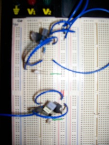
Onto the breadboard I go! An electronics hobbyists best friend. Fairly simple to put together. Plug plug and plug, it’s all together!
Yay! The right voltages… After about half an hour playing around wondering why I was getting 0V all the way through. Turns out plugging in the 7805 the right way REALLY helps… That and grounding it… Man I am an idiot…
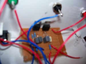
So, it’s all tested and working and whatnot. To the prototype board! Let’s make it a little more permanent. Again, fairly simple? Not when Phill’s been drinking!
For starters, the prototype board that I chose to use had the worst track layout I have ever seen. I spend almost an hour just planning how to get it onto the board! If I had been smart, I would have taken a photo of the tracks, but I didn’t think of that, so just imagine the worst layout of copper tracks you can.
So, everything has been placed. Time to solder! I am ashamed to say, this job was some of the worst soldering I have ever done… Shit was going everywhere… Doesn’t help that halfway through I lost the spring out of my solder sucker, So it became really hard to get rid of the excess solder everywhere. *facepalm* I still haven’t found it…It was on my desk, but then it wasn’t…
So I solder everything together. Plug in the power, and… Nothing. Again. Nothing. Tonight was just not my night.
Break out the old multimeter, trace the voltages through it…What do I find? 12V has sneakily joined up with the ground somewhere…
Keep looking. Where can 12 be getting through? Bloody hell. Half an hour later. I also find that I didn’t ground the 7805… again. Fix that up… Still nothing… Turns out I joined the wrong two tracks together underneath the 317. I connected the input and ground lines, instead of the ground and output line… I am on a ball tonight… Fix that. Viola! Working! Finally!
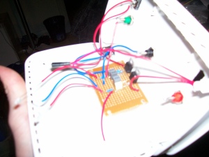
Now. What can I stick it in? The power supply you dirty minded fool. Look around for a suitable container. What do I see? A dead modem! Small, yet plenty of space for my little circuit. Get hacking with a drill and jigsaw blade. Cut some holes for the terminals and switches. Hot glue the circuit and LEDs in. Screw the terminals in. Pop in the switches. Easy!
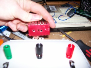
Now, as you can see in one of the pictures, I have a heat sink to attach to the regulators, but as I am lacking thermal paste and little nuts and bolts to attach them to the heat sink, for now I’m just going to hope it doesn’t overheat. Shouldn’t unless I draw excessive current and have my input voltage rather high.
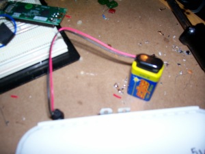
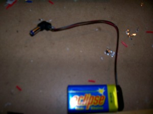
Also, you can see I made a little 9V battery adapter to make the whole power supply somewhat portable. You never know. Might come in handy one day.
Well. That’s that adventure over with. I now have a handy bench supply of 5V and 3.3V. Now I’m going to fiddle with the accelerometer on my TI MSP430 board from last post.
Keep it real.


