Category: Random


F***en Magnets…

gettingstuffdone.jpg

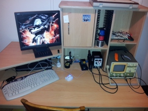
On Friday I bought an old oscilloscope from Uni on the cheap. That and a old Wishmaker, with a signal generator, variable voltage supplies, switches, buttons, multimeter and a breadboard. Getting all this home, I quickly realised that I didn’t actually have enough room on my desk for all this stuff. Sad Panda. So what do you do? Move into the spare room and use the desk sitting in there! (nearly) Instant workspace!

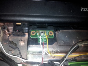
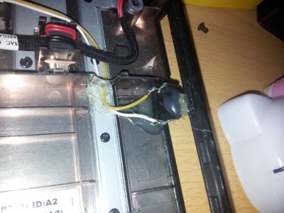
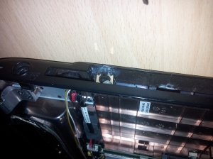
Need a computer for said workspace… For datasheets and coding and what not. I know! I’ll use the broken screen laptop curently on my desk and wire it up onto my workspace instead! But what about powering it on and applications? I’ll, shudder, need a windows boot, I use to use Wake on Lan to turn it on becuase it was just a hassle to open up the screen and press the power button, especially when the monitor was resting on it. Moving it to the spare room meant that I coudn’t run an ethernet cable to it, so Wireless had to be used. WoL doesn’t work on wireless. Well. Atleast not with this old Toshiba laptop. But. I got the bright idea to break out the power button to outside the laptop case. Simple enough really. Tack a new momentary button onto the power button board in the laptop. That was the easy part.

What was the hard part, was the power button wouldn’t work when the lid was closed. Some smart developer decided to disable to power button when the lid was closed. This kinda defeated the whole purpose of the new button, didn’t it? Yeah.
So several hours of hunting around the laptop trying to find the sensor got me REALLY frustrated. Other laptops I have pulled apart had simple switches in the hinge or a basic light sensor. This one, had none of these. No obvious sensors, no hidden switches, nothing.
After pulling, literally, everything apart and unplugging everything, I still couldn’t find the sensor. It had to be in the monitor somehow because nothing else placed over the laptop with the monitor removed would set the sensor off. But it couldnt be in the monitor because nothing was plugged into the monitor. Even after stripping the camera, LCD and mic out of the screen section, it still was sensing some how.
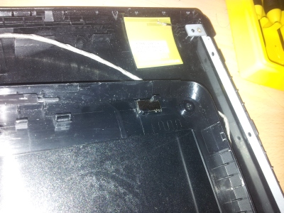
Genius here decides to look on the other side of the bezal that he just put back onto the screen. Low and behold. What was there?
A Frikken magnet. There was obviously a magnetic sensor on the board that detected when the magnet was near by and set laptop to sleep/disabled power button.

It’s kinda hard to see, but it’s the dark silvery bit clipped into the screen. Pop that out.

Bam, it works. That’s it. On the upside, I got rather intimate with a laptops guts, but I am never pulling this one apart again…

Dual boot! This was also far too painful. Because it already had Ubuntu installed on it, installing Windows will destroy the GRUB2 bootloader, rendering the Ubuntu partition useless. But that’s easliy fixed, right? Wrong.
Install Windows, that goes painlessly. Try to repair the GRUB2 bootloader using a live CD, same way I have done it many a time before.
Nope.
Doesn’t like that.
Why? Because it reakoned that there was no GRUB installed to it in the first place, which is crazy talk. Crazy talk I tells ya!
After a few more hours of hunting and trial an error, I discover I need to chroot (kinda run the Ubuntu commandline within another linux install) into my Ubuntu install from the live CD and Re-install GRUB completly. Sigh.
Ultimatly it was fairly simple from there. Let me walk you through it.
First we needed to find which partition the linux build was on. Punch in:

sudo fdisk -l

Find the partition that says “Linux Partition” and that’s the one we’ll be using. From here on I’ll be using sda1, because that’s the one mine was.
Next, let’s make a folder to mount everything in.

sudo mkdir /mnt/root

Then lets mount our linux install files to allow us to chroot in:

sudo mount /dev/sda1 /mnt/root<br />
sudo mount -t proc none /mnt/root/proc<br />
sudo mount -o bind /dev /mnt/root/dev

Done. Now to chroot in!

sudo chroot /mnt/root /bin/bash

From here you should have a slightly different looking prompt on the terminal. Here, type:

sudo grub-install /dev/sda

Bam. That fixed it! After a little custom work with the grub loader from inside my Ubuntu build, like changing the time out and looking for my Window partition (sudo update-grub), we have a working GRUB2 loader!

Well, here’s the fruits of my labours. My new workspace!

Updates updates updates!
What have I been doing you ask?
Uni work. Far too much uni work for my liking. Well, it’s done now. For this year at least. So now it’s time for projects, SKYRIM! and work.

Let’s take a step back for a moment and I’ll explain one of my subjects that has kept me so busy. The subject known as ECTE350 Engineering Design and Management. Basically, at the start of the year we are put into teams of 8 and are given a theme. From this theme we must design a product, then build it. Following all regulations, much paperwork and what not. This years theme was “Aged and Disabilities care” and Team 8, also known as TSAM Tech designed and built the E-LINE. Pretty much, it’s an automated clothes line with various sensors to detected temperature, humidity, and light to detect when to draw the clothes line into the house through a window. It was also controlled by a wireless remote to move the line so it was easier for the disabled person to sit in their wheel chair and hang clothes with minimal movement.

Don’t listen to Jaqui. It’s her bra, not a swim top…

Here we can see the E-Line and TSAM Tech Team Members, minus Ru Qui, he missed the photo. We had to present our product at the annual Innovation Fair at UoW and the crowds vote on the products. This year we came third! So pretty much, this past semester at uni all my project mind set has been in this product.

Moving on.

What else. Tried to fix a mates monitor. That didn’t work. Backlights dead and I cannot find any visually dead capacitors. Bought a new Arduino Mini Pro on eBay. Just for shits and giggles. Noticed my TV has serial comms line for RS232 control. Winning! TV/XBMC remote all in one in the thought planning stages…

Yesterday, I started up on my Wireless glove gesture control mouse again. I have dubbed it the “RatGlove”. As it turns out, the learning curve between AVR micro controllers and TI micro controllers is quite steep. Not a huge fan of TIs Datasheets really. Too many references to other documents and poorly documented. I braved the datasheets and got my FR5739 board to work at the right clock speed and set up the USART interface properly so my serial LCD screen works with it all properly like. That took me 2 days alone. Oh well. Next is the accelerometer. I have a much better understanding of the ADC component of micro controllers now after my micro controller subject at uni. Hopefully I can decode the accelerometer stuff this time around.

See? Photographic evidence I am actually doing something other than Skyrim. Notice no super dodgy transistor array this time around, it’s a serial enabled 3.3V LCD available from LittleBirdElectronics. Quality aussie supplier. They get their stock from several other manufacturers, like SparkFun.

That’s pretty much it from me this time around. Just keep blowin’ shit up and taking names.

Imperial March on atmega16

I sat down to do one of my micro-controller labs for uni today and noticed we had to play a single tone using PWM. “Easy” I thought. Keep reading. Until I get to the final part of the lab. it was basically “Load this HEX file and play it. It plays a musical piece” .
I was a little let down…
I mean, I was fully expecting it to ask us to write the program ourselves to play a given song, but no. Here it was just giving us the HEX file to load and play.
I wasn’t going to let this deter me. I had it in my head to have this thing play The Imperial March by John Williams from Starwars.
Mate and I got together, and off we went.

It’s a relatively simple program. 2 arrays holding the frequencies and durations of each note, PWM output, and a loop to play each note in sequence, and then start again.

Bam.

Easy as!
Here’s the source code for anyone interested.

Source Code

This uses about 50% of the atmega16’s memory, becuase of the arrays. So keep that in mind while writing new songs!

Have a go yourself! Port some new songs into chiptunes!
Post your results!

So, I’ve had a bit of an intermittent right bumper on my Nintendo DS Lite for a while now, but a few months ago, it gave up the ghost. Far too much Bleach: The Blade of Fate, and Tetris. Forever Tetris.
My mate and I, whenever we see each other, we play Bleach for hours on end. Never listen to him, I win. BUT! My right bumper broke, and it’s quite hard to win at a fighting game without a block button.

So. It broke on a train on my way home from Sydney. We tried re mapping the block button, mashing the button hoping that it would start working again. To no avail.
Oh well. Mario Kart it is then.
Then it just went to the back of my mind and wasn’t thought about again. Until a few nights ago.
Talking to my mate “Why don’t you just pull it apart and fix it?”
Challenge Accepted.

Hit up Ebay, get me a Tri-wing screwdriver to open Nintendo products. 2 days later, my DS was on pieces on my desk.
Test, test, test. What do I find out? The actual button is fried. Not the bumper playing up. The button has died.
Well. There goes that button. But hang on! I have a couple of spare SPST momentary switches lying around! Surely I can hack one onto the board!

And do that, I did…Here are the results…

I ah…Think I also burnt off a resistor just below the bumper…But it hasn’t affected the operations of my DS what-so-ever. Well, we’ll see in the long run if anything happens.
Enjoy my little triumph, and remember, if it’s broke, it can be fixed. And if it’s not broke, then it still needs fixing.


EDIT: Turns out my power LED has stopped working…Hence, I have no idea when it’s running out of power…
That’s really odd. It was working last night… That could be what the resistor was, but, the LED wouldn’t have worked last night… Hot glue isn’t conductive is it? I don’t think so…
This makes Phill a sad panda.

EDIT AGAIN: Turns out it was the current limiting resistor for the red LED that warns of low battery. The green power and orange charging LED still work perfectly. So i’ll just have to remember, if no LED is on. It’s either not on at all, or it needs charging…

Remember last post I said I was going to play with the accelerometer on my TI board? Well, I didn’t lie too much…
I decided to wire a LCD screen up to the board so I could see the data from the accelerometer in real time. That was hard enough…As this post is detailing.

Two days.

That is how long it took me to realise 3.3V logic and 5V logic doesn’t play well together. Two of them.
Let’s take a few steps back and I’ll start from the start.

I wanted to play with the accelerometer on my TI board, but I like seeing what’s happening. The data in/out. What everything is doing. The awesome JFET debugger on the TI board helps a lot with that, but nothing beats a good old LCD screen showing what’s happening. So I thought, “I’ll just grab an LCD screen, hook it up and then play with the accelerometer”.
Good idea idiot.
Armed with my new 5V power supply (Which, turns out, did need the heat sink. That 7805 gets frikken hot) I set out to quickly hook up my LCD screen to my TI board.
Nope.
For starters, it was a different LCD screen to the first one I had. So all the commands are different, the initialisation is different, the pins are different. After making a massive spaghetti mess of cables to connect the screen up I set out to write some code.
Enter first problem.
I don’t know how to code on TI microcontrollers. I don’t know the routines, the registers, the tips and tricks. Oh I know C syntax. I can code. But not on TI controllers. Just starting off and getting a simple code to compile and run was interesting enough. But I digress. After poking around in the example code that came with the board, I worked out how to set up the Data Direction Registers, well, the TI equivalent anyway.
I cracked out the code I used for the other LCD screen I used previously in my Bluetooth remote. The logic was useable. Had to play around with the pulsing of the enable logic for it to work on the TI compiler. Along with writing my own “delay_ms” and “delay_us” functions.
So. Technically, I have functions that should work. The wires are all connected together properly. Trust me. I had checked those wires about one hundred times.
Still nothing is working.
I couldn’t even get the LCD to initialise.
Nothing.
Farq.

End day one.

I know!
I’ll hook the screen up to my ATmega8515 on my STK500 and see if I can get it working. Low and behold. It works. The screen initialises and prints text. (After much fiddling around and making an LCD header and source file, just for future use, I might post it up here once I have commented and cleaned it up a little.)
So what am I doing wrong on the TI board?
Move it back and try the new logic from the AVR program.
Still nothing. It’s not the contrast adjust. I play with that every time I try to get it work, tuning it to try and get some text to appear. So what the hell can it be?
Late at night after watching some Starwars, possibly episode 3, maybe 2, it dawns on me.

TI uses 3.3V logic.

Fark.

Really?

That’s it?

Really?

Farq.

End day 2.

This is damn “simple” project is now testing every part of my engineering mind, and it turns out to be a simple little thing like that? I am going to make this thing work if it kills me.
Right. Now I have established I need 5V logic for the LCD and my TI board outputs 3.3V logic, what can I use to bump it up?

A series of 7805’s? Pfft. No. That’s expensive and just silly. Also, The response time would be far too slow. Probably. I didn’t have any spare 7805’s to test it with anyway.

What I need is a way to use 3.3V to switch on 5V.

Hang on.
Isn’t that what transistors are for? Digital switches?(actually, they are current amplifying devices, but can be used as switches, and commonly are) Humm…. I remember playing around with this for a night. Where was that video I watched?
Here!

Right. There’s the kinda thing I need to do. How can I adapt that to work with logic? Think Phill! That’s all your mind ever does! Think!

Aha!

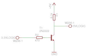
Remember this post? It’s a switch! For logic! I’ll just replace the mechanical switch with the transistor! Genius!

A transistor array!

The actual transistors I am using are c1815. A small signal audio amplifier. Not really the most optimal for a transistor switch, but what I had with me anyway. Still works.

But hang on. This will invert the logic. This design makes the output active low with active high input. This had to be reflected in code, obviously. But if you do this hack method, remember to invert your output.

Right. Let’s get this baby working.

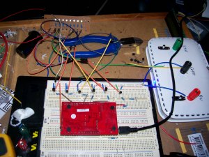
Look at that!

My pretty TI board and my transistor array are being nice together. After I realised I had to ground the R/W line on the LCD screen. Silly mistakes for everyone! I have enough spare!

So there you go.

After 3 and a bit days of fiddling around. I have a working 5V logic LCD screen interfacing with a 3.3V logic TI microcontroller.

Finally.
Hope you enjoyed this epic post of silly mistakes. Proving, you can interface 3.3V logic with 5V logic.

EDIT: I had better point out, this is a one way logic converter. For output from the microcontroller only. You can’t read anything in from the screen using this method.

P.S.
I still haven’t found my spring from my solder sucker. Curses!

Bench Power Supply

Well, I got off my arse and designed and built a little bench power supply. Just a quick little thing capable of outputting 5V @ 1A and 3.3V @ 1.5A (Assuming you have a wall pack capable of outputting that much current).
It has pretty much no over current protection or anything fancy like that. The only protection in it is what is built into the voltage regulators. As I said. It’s simple. Schematics!

As you can see, a simple LM 7805 and LM 317 configuration with smoothing capacitors. Pretty LEDs to show that its working, a couple of switches to turn each segment on and off as needed and input power from a wall pack. To calculate the resistance needed on the 317 to get your desired voltage, simple use one of the many online calculators. The input voltage can be anything above 7V if you want to use both voltages. If you just want to use the 3.3V line, 5V input will be sufficent.

Throwing it together.
Onto the breadboard I go! An electronics hobbyists best friend. Fairly simple to put together. Plug plug and plug, it’s all together!

Yay! The right voltages… After about half an hour playing around wondering why I was getting 0V all the way through. Turns out plugging in the 7805 the right way REALLY helps… That and grounding it… Man I am an idiot…

So, it’s all tested and working and whatnot. To the prototype board! Let’s make it a little more permanent. Again, fairly simple? Not when Phill’s been drinking!
For starters, the prototype board that I chose to use had the worst track layout I have ever seen. I spend almost an hour just planning how to get it onto the board! If I had been smart, I would have taken a photo of the tracks, but I didn’t think of that, so just imagine the worst layout of copper tracks you can.

So, everything has been placed. Time to solder! I am ashamed to say, this job was some of the worst soldering I have ever done… Shit was going everywhere… Doesn’t help that halfway through I lost the spring out of my solder sucker, So it became really hard to get rid of the excess solder everywhere. *facepalm* I still haven’t found it…It was on my desk, but then it wasn’t…
So I solder everything together. Plug in the power, and… Nothing. Again. Nothing. Tonight was just not my night.
Break out the old multimeter, trace the voltages through it…What do I find? 12V has sneakily joined up with the ground somewhere…
Keep looking. Where can 12 be getting through? Bloody hell. Half an hour later. I also find that I didn’t ground the 7805… again. Fix that up… Still nothing… Turns out I joined the wrong two tracks together underneath the 317. I connected the input and ground lines, instead of the ground and output line… I am on a ball tonight… Fix that. Viola! Working! Finally!

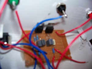
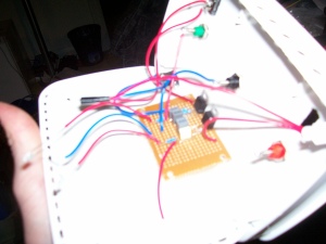
Now. What can I stick it in? The power supply you dirty minded fool. Look around for a suitable container. What do I see? A dead modem! Small, yet plenty of space for my little circuit. Get hacking with a drill and jigsaw blade. Cut some holes for the terminals and switches. Hot glue the circuit and LEDs in. Screw the terminals in. Pop in the switches. Easy!

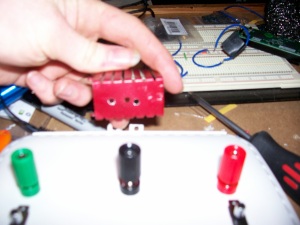
Now, as you can see in one of the pictures, I have a heat sink to attach to the regulators, but as I am lacking thermal paste and little nuts and bolts to attach them to the heat sink, for now I’m just going to hope it doesn’t overheat. Shouldn’t unless I draw excessive current and have my input voltage rather high.

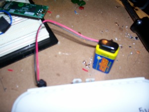
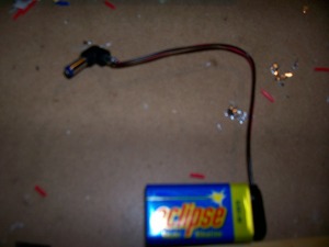
Also, you can see I made a little 9V battery adapter to make the whole power supply somewhat portable. You never know. Might come in handy one day.

Well. That’s that adventure over with. I now have a handy bench supply of 5V and 3.3V. Now I’m going to fiddle with the accelerometer on my TI MSP430 board from last post.

Keep it real.

Ahh. Holidays. What better time to fiddle with projects?
Not a lot to report on the project front today. More of a quick update on my analog meters, planned projects and new toys.

Remember last post I talked about making new covers for the meters?
Well! Here they are!

Purty no? On the upside, I learnt GIMP doesn’t like doing colour inversions, but paint does… Riddle me that internet, riddle me that…

That’s the only update I have for you on that project. I have kinda lost some inspiration on the SD card logging when I couldn’t get some example codes working. Just needs more time than I have had recently.

Moving right along!
New projects!
What are several things a electronics hobbyist needs?

  • Soldering Iron
  • Multimeter
  • Oscilloscope
  • Bench Power Supply

Yes? We are in agreement? Ok, maybe not the oscilloscope quite that much, but still. Would be pretty handy…

So I have a solderin iron. It’s old and the tip is burnt through, but it works pretty well. Multimeter? Check. A cheapo $20 one picked up from leading edge electronics when I was 12 I think… Once again. It works to everything I need it to, so far. Oscilloscope? I wish… I’m saving for one at the moment. A cathode ray would be awesome, but I just don’t have the space. So lately I have been thinking of and looking at the digital scopes. As of yet, I don’t know. Peoples thoughts?

Now. Bench power supply. That, I am missing. At the moment I just use the 5V line from my arduino. That’s not really the best way to do things due to the current limitation from that line. We don’t want to be burning out my arduino board now do we? That would just be inconvenient.

So. what to do? A variable bench supply is too expensive. I could mod an ATX powersupply to feed me the 5V and 12V lines from the molex plugs, but the only spare ATX supply I have is dying and they draw a bit of power even with no load attached.
What to do?
Enter brilliant idea.
Build a simple 5V and 3.3V power supply.

Using an LM7805 and a LM317 voltage regulators, feed 12V from an old wall power pack I found lying around into the regulators. Take the output from the LM7805 for 5V, output of LM317 as 3.3V, output direct from the wall pack as 12V. Throw some regulating capacitors and backwards current protector diodes in. Throw a heatsink on the regulators just in case. Simple! I can even build a little adapter to plug in a 9V battery instead of the wall pack. Some pretty LEDs in and switches to turn each segment of the supply on or off. Best idea ever. Best thing is, I have most of the components! Just not the important ones. Like the LM317 and the capacitors… Looks like I’m going back to Jaycar.

After a bit more research I will be ready to draw up a proper cicuit diagram.

Onto my new toy. 😀

Thanks to a post at Hack A Day, I managed to pick up a Texas Instruments experimenter board for half price. Only $13.66! That included shipping! An offer I could not refuse.

The board was a MSP-EXP430FR5739. This board was developed to show off a new(ish) system of memory called FRAM (Ferroelectric Random Access Memory). FRAM boasts a write endurance of 100,000,000,000,000 cycles. What the hell? Thats a huge number. Over 100 billion times more than FLASH memory. That thumb drive with all you back-ups isn’t looking all that safe anymore now is it?
FRAM also writes a hell of a lot faster than FLASH. like, 100 times faster.

You must be thinking, “If FRAM is so good, why do we still use FLASH memory?”
I’m glad you asked that.
While FRAM is more reliable, faster and uses less power, it also have several flaws.
As with all new stuff, It’s expensive! That is the main point in it not taking over FLASH. No one likes spending lots of money, especially big corporations who cut corners to save 1c per product…
Capacity. It just doesn’t, at the moment, have the same capacity for storage compared to FLASH.

That’s enough of me plugging the FRAM. On to plugging the experimenters board infront of me.
This little baby is a 16 bit RISC architecture MCU running at 8MHz. On the board there is a 3 axis accelerometer, a thermistor, 8 LEDs and 2 switches. Other TI boards can be connected to it via a couple of header plugs at the back of the board. All PC and USART conections go through a micro-usb plug at the top of the board. Power is also drawn from USB.

Wow that’s a piss poor photo. Man, I need a new camera…

3 axis accelerometer and a PC interface? I think a gesture control for my PC is on the cards…

Well enough from me today. This short post turned into quite a long one. I should probably go do the washing up now… Have fun!

Why I Think Earth Hour Is Bullshit

Ok, well, that’s a half truth. It is a fantastic tool for raising awareness of our power consumption, the act of turning our electrical devices off for an hour and then back on again is, well, stupid. In most cases, it takes less power to keep an electrical device on for an hour than to turn it off and on.

Let’s look at the theory a little bit. Apologies, this will get real technical, real fast.

We have 2 energy storage components in our electrical circuits. No, I’m not talking about batteries, I’m talking about capacitors and inductors.

Capacitors, through use of parallel, electrically charged plates, store “Voltage” (The mere concept of “storing” voltage is silly, but to keep things a little simple, let’s assume we can).
Your thinking, “Ok Phill, that’s cool, how does that mean it’s bad?”
I’m glad you asked faithful reader.
Think, at initial conditions, t = 0, before we turn on the circuit, it contains NO charge. It’s just chillin’ there. We throw the switch, suddenly the capacitor starts to charge. The voltage across it increases at an exponential rate. At V = E(1 – e^(-t /τ)), where E is the source voltage, t is time and τ is the time constant of the given circuit (τ = RC). The capacitor will reach full charge after 5 time constants, so depending on how complex the circuit is, it will take longer to charge.

Ok, now to the other side of the coin, capacitors also draw current! Yes! But ONLY when they are charging. Now this is at a rate of I = (E/R)e^(-t/τ) , where R is the circuit resistance and again t is time and τ is the time constant.

Right. Now, Power. What everyone is going on about with “Earth Hour”. Power of a circuit is defined as P = VI. Voltage times Current. So, looking back at our capacitors, we have a device that will draw a large amount of current starting out, then drops down, and the voltage starts out small and moves up. You think “That’s ok, they will cancel each other out”. Nope.
Voltage of the ENTIRE circuit. You will have other components drawing current and requiring voltage. So the voltage of the circuit, with a suddenly applied voltage source, will still be larger than the voltage of the capacitor. Therefore, at t = 0+ (Just after we turn on the circuit), we have a large current draw with the same voltage, resulting in a large power draw, via the relation of P = VI.

Inductors are essentially the same, except they “store” current. So the current flow through them drops exponentially and the voltage rises exponentially. So the same problem applies with the P = VI.

Now that’s out of the way, how does this effect anything?
Well. The basic structure of an AC-DC power supply is a Bridge rectifier (1.4V drop at all times), Transformer (A really big inductor, yeah, it has inductance) and a set of Capacitors. You turn on, say, your phone charger. To you, it works instantly, to the device, it has a “start up time”. The capacitors in the circuit need to reach their charged state, the transformer needs to warm up. All this takes more power than required to maintain its state of equilibrium.
This power supply structure is in almost EVERY device you plug into the wall. AC is easier to transport, but DC is much more useful in everyday applications.

Well. That’s power supplies out of the way, let’s look at lights.
Those “Power saving” fluorescent globes you buy? Yeah, the ones that take age to start up…
They require an extremely large voltage to turn on. They’ve got little “Starters” in them that convert large current flow into a large voltage spark to turn them on. Now, P = VI. Large current OR voltage flow means…Large power draw. Once they have reached their state of equilibrium (after 3 mins i might add) then they settle down. They still draw a very distorted current, which, trust me, is bad. You aren’t paying for the distorted part, but the power companies still need to generate it and pay for that. But we’ll get back to the power companies later.

“But Phill, I don’t like them, so I have plain old Incandescent globes”. Well done, I salute you. I hate the power savers. That’s more personal opinion though. You’re still not off the hook. The Incandescent globes are made by making tiny coils of tungsten, and hence, making a small inductor. Again, P = VI, la di da. Drawing large power at start up. There is also another thing to keep in mind. As temperature increases, so does resistance. Now those globes get mighty hot don’t they? Well what about when they have been turned off for a while? They are cold. Therefore, resistance is lower, therefore, a higher current draw (Based on fundamental law of electronics, Ohms Law, V = IR. Or as we are using it here, I = V/R ). The element heats up, resistance gets higher, less power draw.

Well. That’s the maths behind the circuitry done, let’s look at the economic side, yeah?

Power distribution is done by 3 different companies, or branches. There is the company that generates the power, the company that distributes the power, and the company that provides it to you.

The providers buy the rights off the distributers, who buy their power from the generators. Now, this happens on the hour, every hour. The distributers have to guess what the next hours power draw is going to be, and buy that much power off the generators, who will take power generation plants up and down to meet the demands of the suppliers.
So, if we have a massive dip of power draw, the generators will lose money, the distributers will lose money, and the suppliers will lose money. NOT just from you not using power, but because

  • To shut down the generators, for even an hour cost a fortune. But they can’t leave them running because no one is buying the power.
  • To turn the generators back on, there is again, inductors and capacitors, in the systems. Now, generators are HUGE inductors. How much current do you think it takes to get it up and running again?
  • Power factor correction.

“Power factor correction? What’s that?” That my friends, is the bane of power generators and distributors around the world. When you plug something that has an inductor or capacitor in it into your wall socket, it will draw both real current, and an Imaginary (Complex) component. You, as a consumer, only pay for the real power you draw, but the distribution company has to buy real AND imaginary current from the generators. To combat this, for every capacitor and inductor you plug in, they plug the opposite in. This evens it out to mostly real power draw. That is power factor correction. Now imagine turning everything off suddenly. Suddenly the distribution and generation companies are drawing FAR too much imaginary power. Power that still needed to be generated. Power that you are trying to save by turning everything off. So they correct this buy unplugging all their capacitor banks so it’s just back to real power.
Then you turn everything back on. Suddenly they are drawing the large imaginary power again. Again, they still have to generate that power. So they have to plug all their capacitor banks back in. Massive energy  and money loss for the major companies. Who do you think they will pass these “Savings” on to?

Well, I’ve defiantly rambled on for FAR too long. Suffice to say, during Earth Hour, I’m not turning ANYTHING off. I won’t be turning anything on either. Got to maintain the Equilibrium.

Welcome

Welcome readers, welcome to the lab of an Insane Ginger.

I recently got my hands on a Atmel AVR STK500 development board. The aim of this blog, is to document my journey through making some awesome stuff.

Enjoy, feel free to comment! The more I know the better!